预计阅读时间: 0 分钟
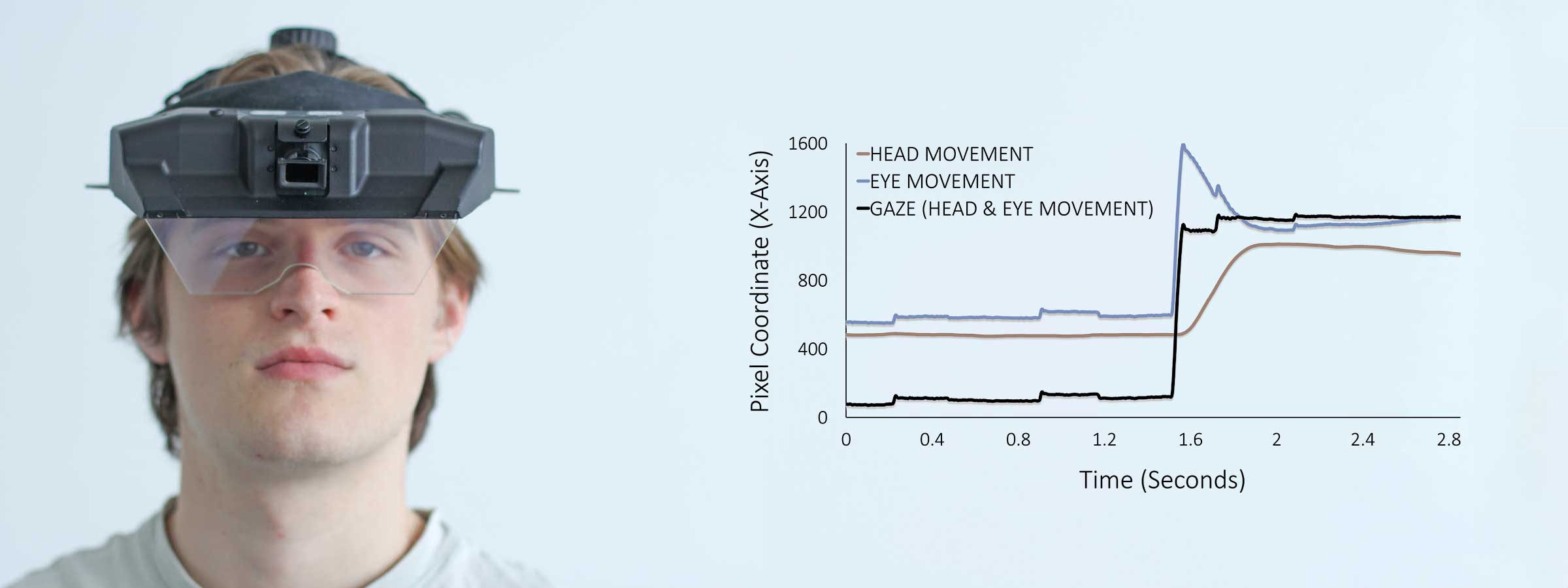
The EyeLink 3 simultaneously tracks both eye and head movements at up to 1000 Hz. The standard six degrees of freedom (6DOF) head data provides X, Y, and Z coordinates (in mm) as well as roll, pitch, and yaw angles. For information on the EyeLink 3 head position and rotation data, please visit our comprehensive blog on 6DOF head tracking.
Like all EyeLink systems, the EyeLink 3 delivers precise gaze data in screen pixel coordinates, where (0, 0) marks the top-left corner and the bottom-right reflects the full screen resolution (e.g., 1920×1080). In addition to standard gaze data, and 6DOF head pose data, the EyeLink 3 also provides separate head and eye-in-head positions in screen pixel coordinates. This innovative feature allows for a simple and clear analysis of the relative contributions of both head and eye movements to shifts in gaze.
In this blog we explain the three pixel-based coordinates (gaze, head 和 eye) that the EyeLink 3 provides.
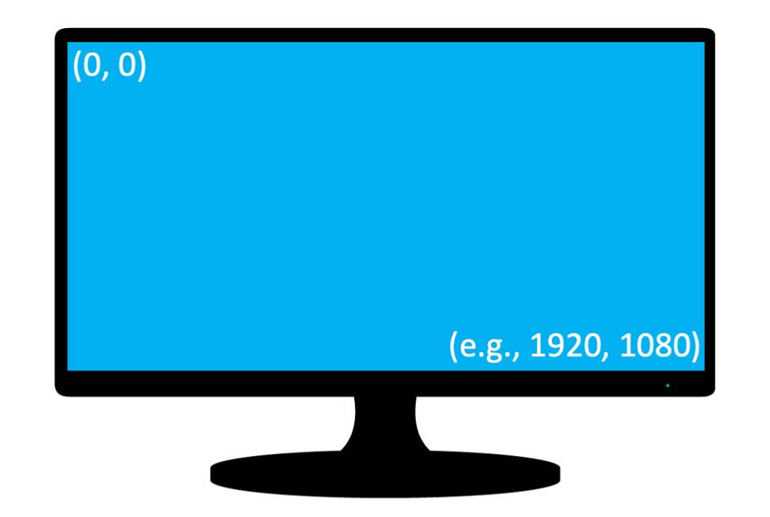
Figure 1: (X, Y) screen coordinates for eye tracker data with (0, 0) representing top left corner and bottom right depends on pixel resolution (e.g., 1920, 1080).
Gaze
In eye tracking research, “gaze” refers to the point of regard on a screen and reflects both the head pose (its position and orientation) and the eye rotation within the head. Below, the images illustrate the effect of head and eye movements on gaze. The first picture, with the person staring straight at the camera, shows the base position with no head movement nor eye rotation within the head. The second photo illustrates gaze to the model’s left after a leftward head movement only, while the third picture also captures gaze to the left but this time as a result of only eye rotations. Finally, the last picture conveys a centered gaze position after a head movement to the left and eye rotations to the right.
Figure 2: Gaze in natural portraits reflecting a combination of head and eye movements.
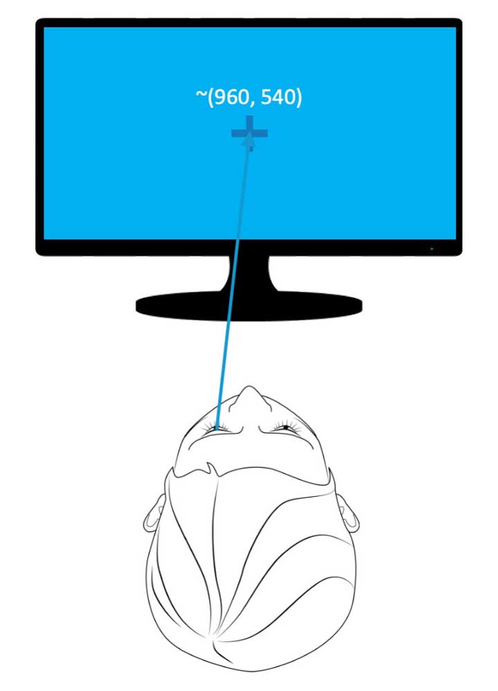
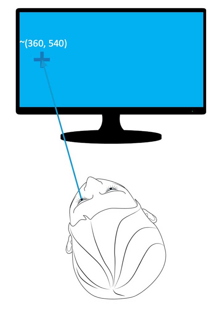
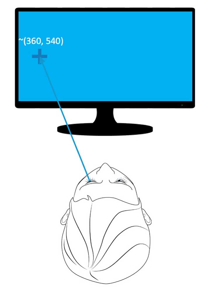
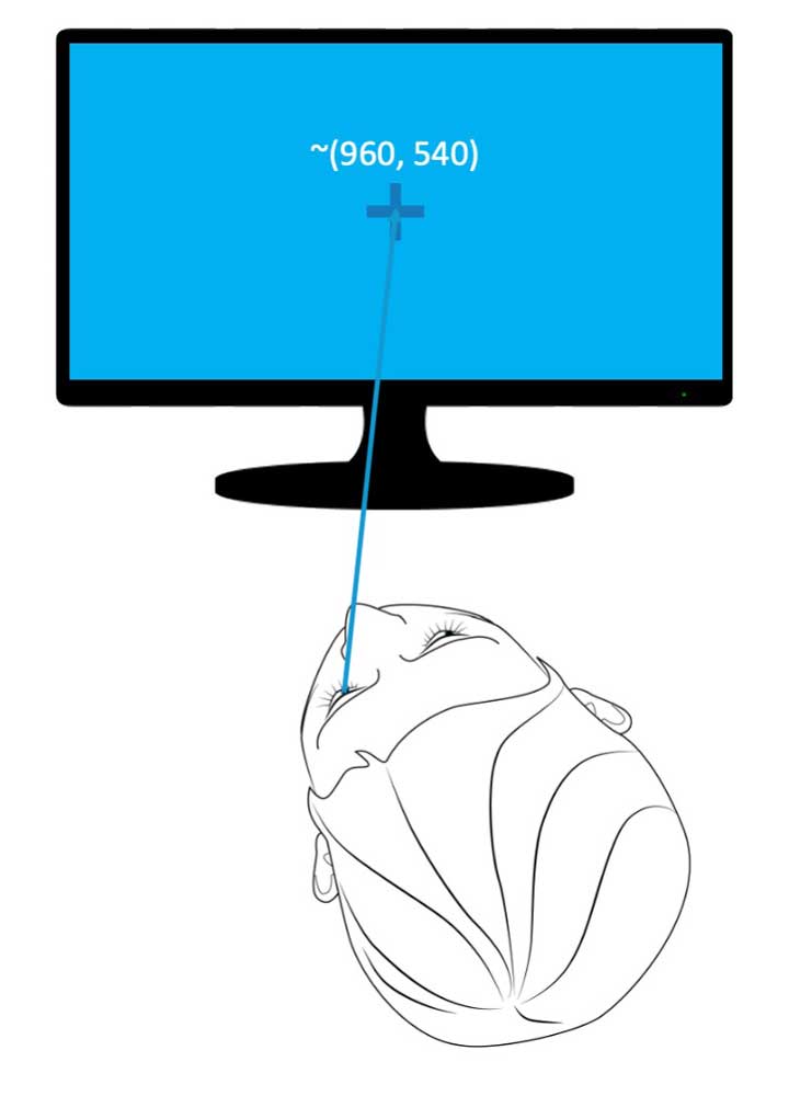
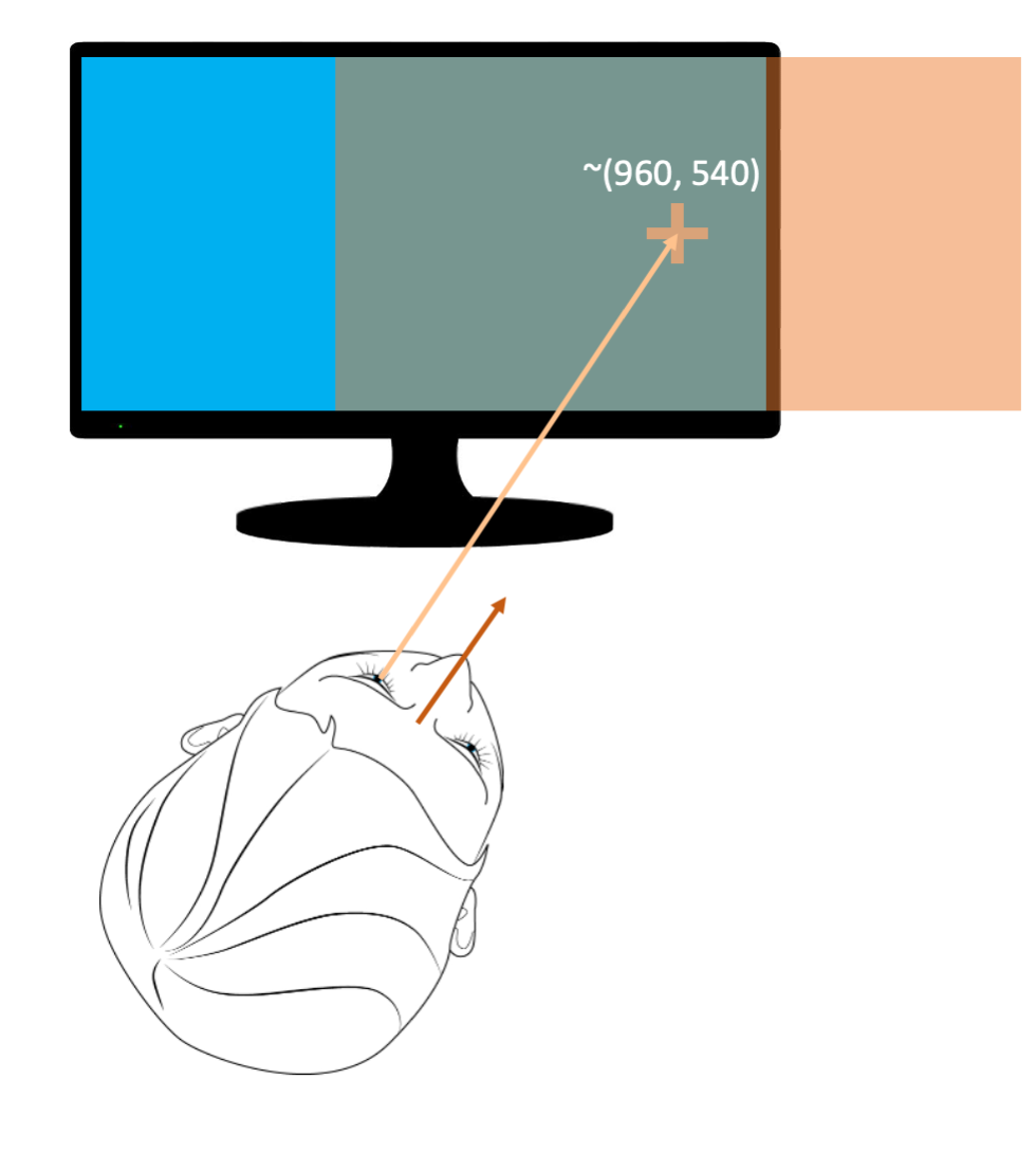
To capture the gaze coordinates on a screen in an experimental setting, imagine a virtual rod extending from the back of the eye, out through the pupil, and towards the screen. The point (or pixel coordinate) at which this rod intersects with the screen is the gaze coordinate. In the first example below, assuming a 1920×1080 pixel screen, the gaze value would be close to (960, 540) because the person is fixating the cross in the center of the screen. The next two images show a gaze pixel value of roughly (360, 540). The gaze shift to the left of the screen is driven solely by a head movement in the second image while only by an eye rotation in the third image. Finally, the last image shows a central fixation (960, 540) again, but this time, the gaze position reflects the combination of a leftward head movement and rightward eye rotation. All gaze coordinates reflect both the angle of the eye in the head and the angle of the head itself. Most traditional eye-tracking experiments will base their analyses on gaze data.
Figure 3: Gaze varies as a function of both head and eye movements. To capture gaze pixel-based coordinates on a screen, imagine a virtual rod extending from the back of the eye, out through the pupil, and towards the screen. The pixel the rod touches provides the gaze coordinate.
Head
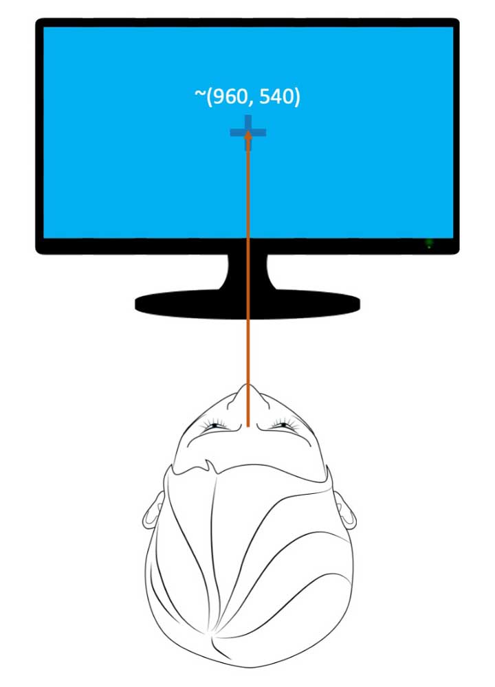
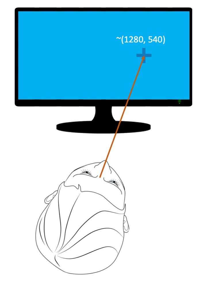
In addition to the standard 6DOF head pose data provided by the EyeLink 3, an indication of the participant’s head pose can also be provided in screen pixel coordinates. For the head pixel-based coordinate, picture a virtual rod extending forwards from between the participant’s eyes towards the screen / calibrated plane. The point at which the rod intersects with the screen provides the head coordinate. For example, in the first image below, again assuming a 1920×1080 pixel screen, the head pixel-based coordinate is approximately to (960, 540) because the person’s head points to the center of the screen. In the next image, the head pixel-based coordinate is roughly (1280, 540) because of a head shift toward the right. As with gaze data, the novel head pixel-based coordinate data provided by the EyeLink 3 may be negative (if the virtual rod intersects the calibrated plane above or to the left of the screen) or exceed the pixel resolution of the monitor (if the virtual rod intersects the calibrated plane to the right or below the monitor).
Figure 4: To capture head pixel-based coordinates on a screen, imagine a virtual rod extending from the center of the head towards the screen. The pixel the rod touches provides the head coordinate.
Eye
The eye pixel-based coordinate is another novel concept unique to the EyeLink 3. It represents the contribution of the eye’s rotation to gaze. Conceptually, it can be likened to using a desktop EyeLink eye-tracking system with a head support – when the head is immobilized, the only contribution to gaze is from the eye movements. However, if the head is not restrained, both head and eye movements typically contribute to gaze. The eye pixel-based coordinate allows the relative contribution of the eye rotation to the gaze location to be determined.
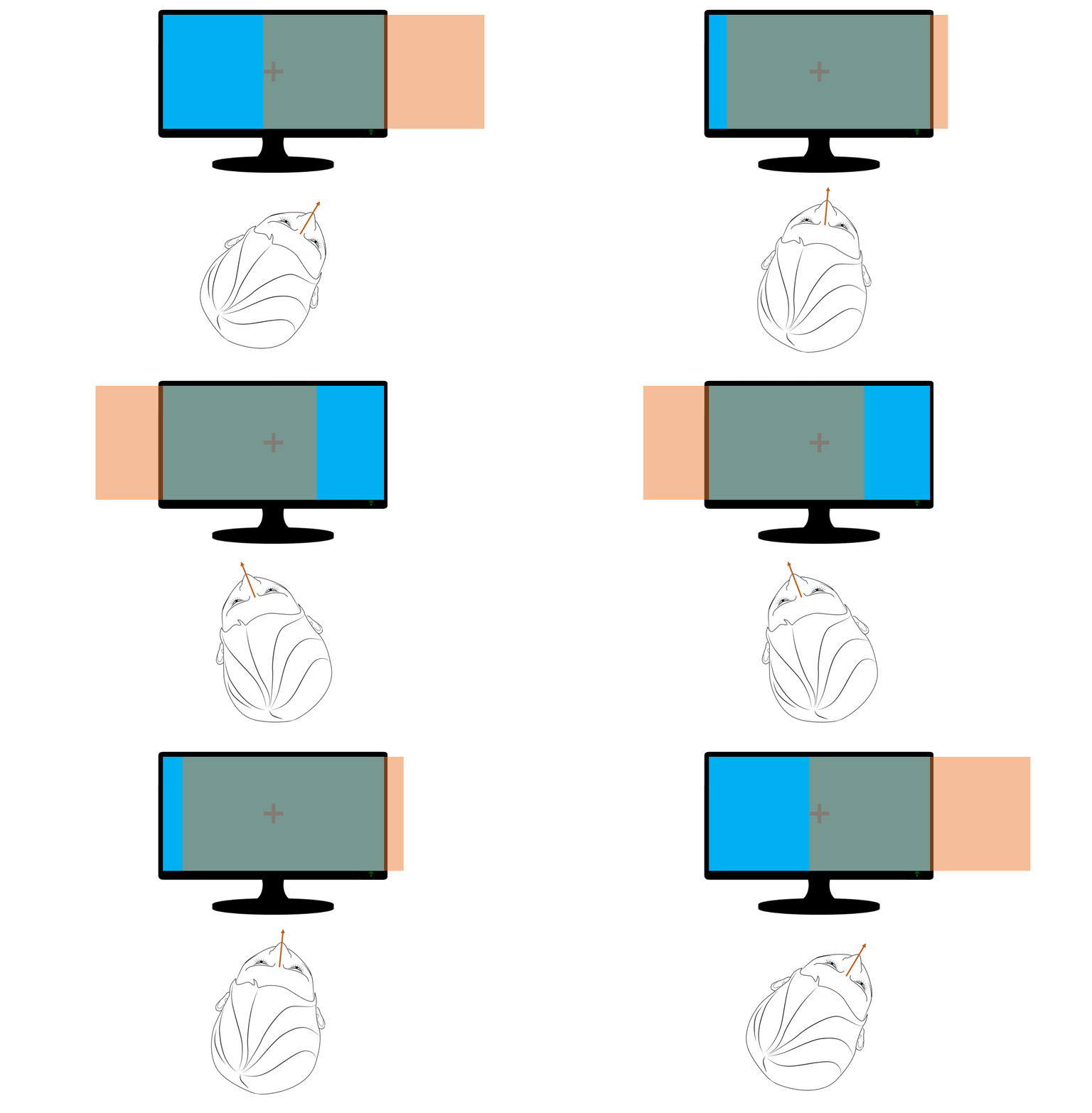
The eye pixel-based coordinate metric represents the rotation of the eye within the head. Imagine a virtual screen that is the exact size of the physical screen, and which is yoked to a participant’s head. In other words, this screen moves with the person’s head – see the orange screen moving with the head below. Note that in the illustration below, the virtual screen movement is only along the X-axis, but the virtual screen can also move along the Y-axis.
Figure 5: To capture eye pixel-based coordinates, first imagine a virtual screen tethered to the head moving along X- and Y-axis. (Note, the illustration only shows movement along the X-axis.) The eye pixel-based coordinate is the gaze location on this virtual screen
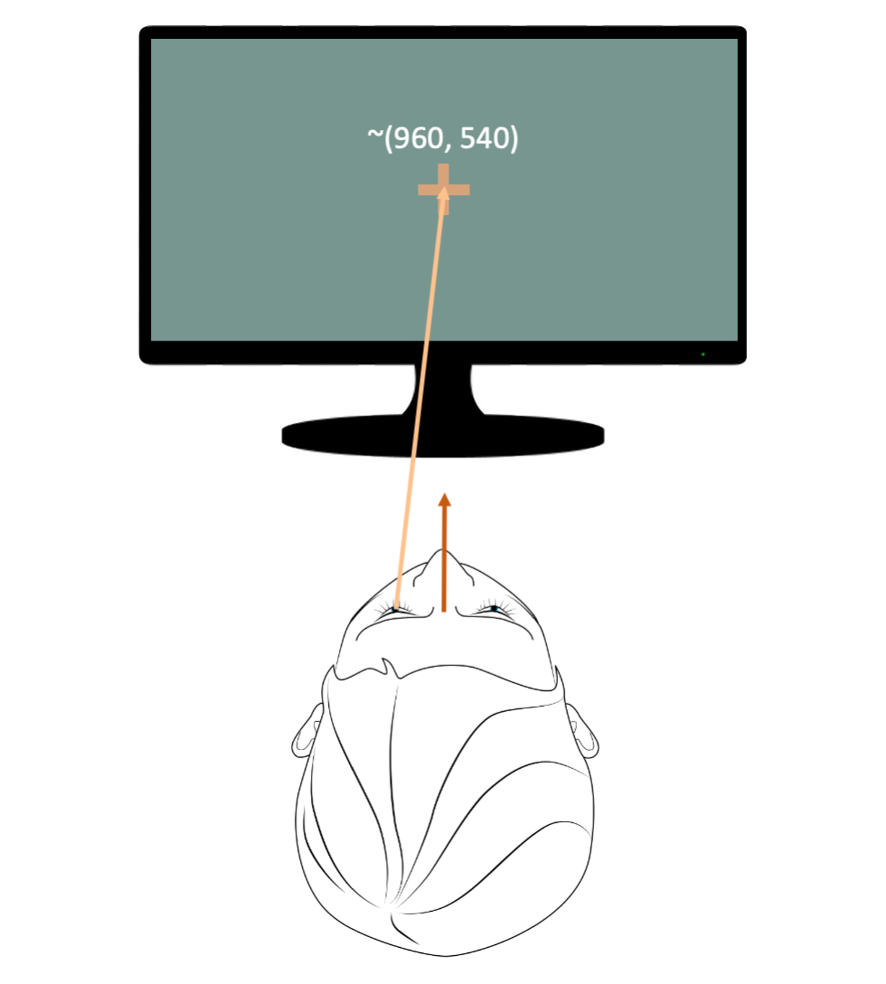
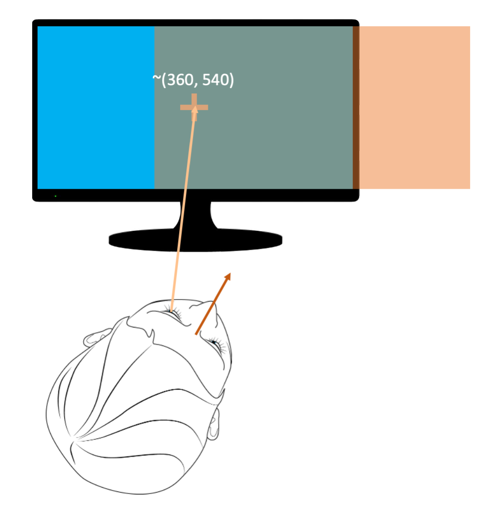
The eye pixel-based coordinate is the location of gaze on this virtual screen (which shares the same pixel resolution as the actual screen). For example, the left image below shows a person staring straight ahead at an actual screen, resulting in gaze 和 head coordinates that are both at the center of the actual screen (960, 540). Because the virtual screen is co-located with the actual screen, the eye coordinates (on the virtual screen) are also (960, 540). In the second image, the head has rotated to the right, but the participant continues to stare straight ahead, at a point on the right side of the actual screen. As the virtual screen rotated with the head, the eye coordinates on the virtual screen are (960, 540), reflecting the fact that the head has rotated to the right, but the eyes continue to look straight ahead – in other words there was no rotation of the eye within the head. The final image shows the person with her head rotated to the right but maintaining fixation on the cross at the center of the actual screen. This involves a counter-rotation of the eye towards the left. The leftward counter-rotation of the eye is reflected in the eye coordinates, which are now to the left side of the virtual screen (approximately, 360, 540).
Figure 6: The eye pixel-based coordinate is on the virtual screen, which is the exact size as the physical screen and which rotates with the head.
Gaze, Head, and Eye Data
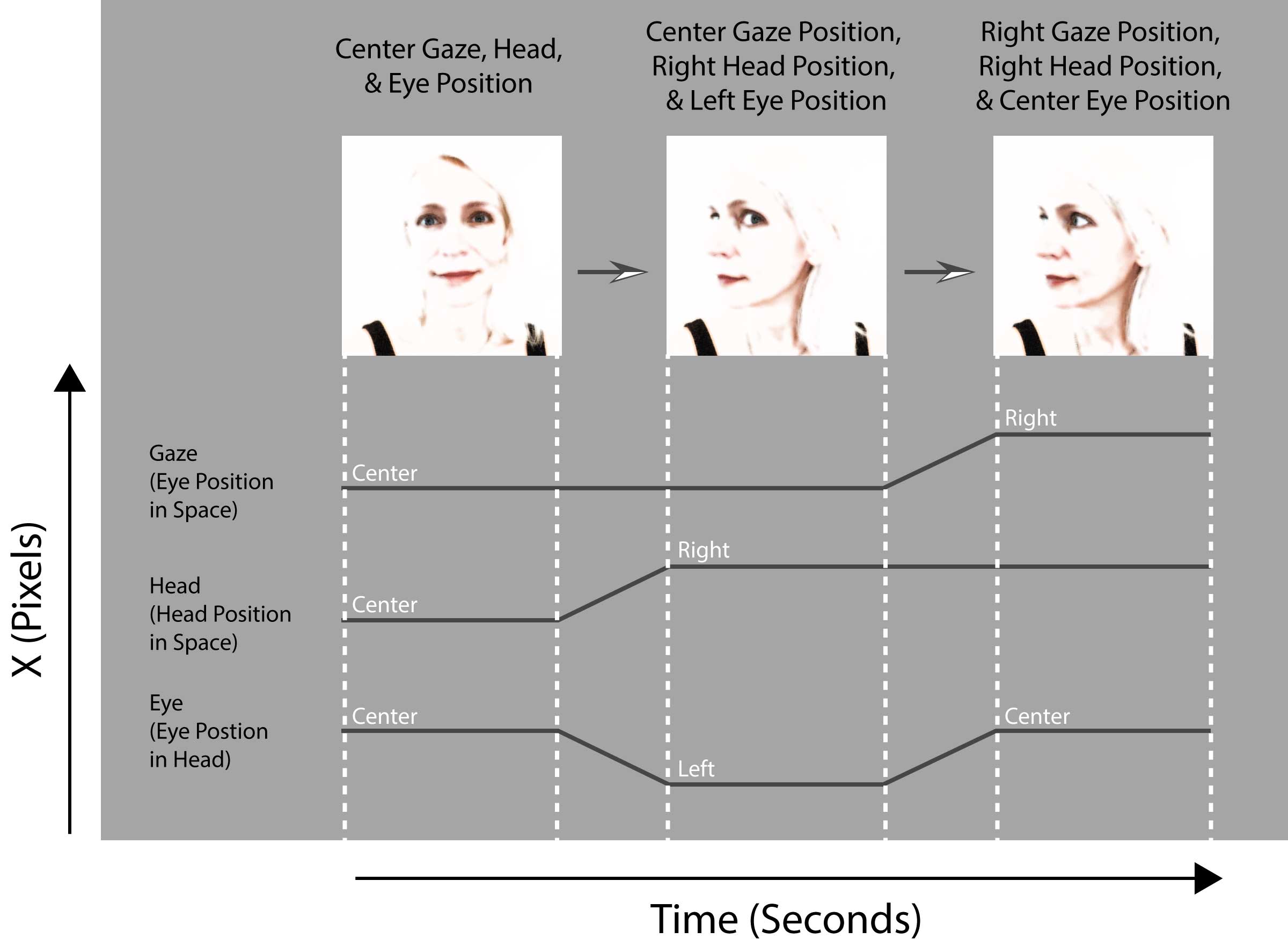
The visual representation below illustrates how the gaze, head, and eye pixel-based data change (along the X axis). The left image depicts a person staring straight ahead at the center of the screen. The coordinates are the same for the gaze, head, and eye positions. The middle image depicts a head turned to the participant’s right, but gaze fixed at screen center. As can be seen in the plotted data, the gaze is still centered at the same screen coordinates as the left image. However, the head rotation is to the right while the eye rotation is to the left (to maintain the central fixation on the physical screen). Finally, the right image depicts the head turned towards the right side, with the participant staring straight ahead. Because the eyes did not counter-rotate (the eye coordinate shows no change), this results in a gaze shift to the right.
Figure 7: Pixel-based coordinates along the X-axis for gaze, head pose and eye movements. Left image shows a person staring centrally, resulting in the same gaze, head, and eye pixel-based coordinates. Middle image shows head turned to the right and eyes rotated to the left to maintain center gaze. Right image shows gaze and head to the right with eye position at the center of the head, not moving.
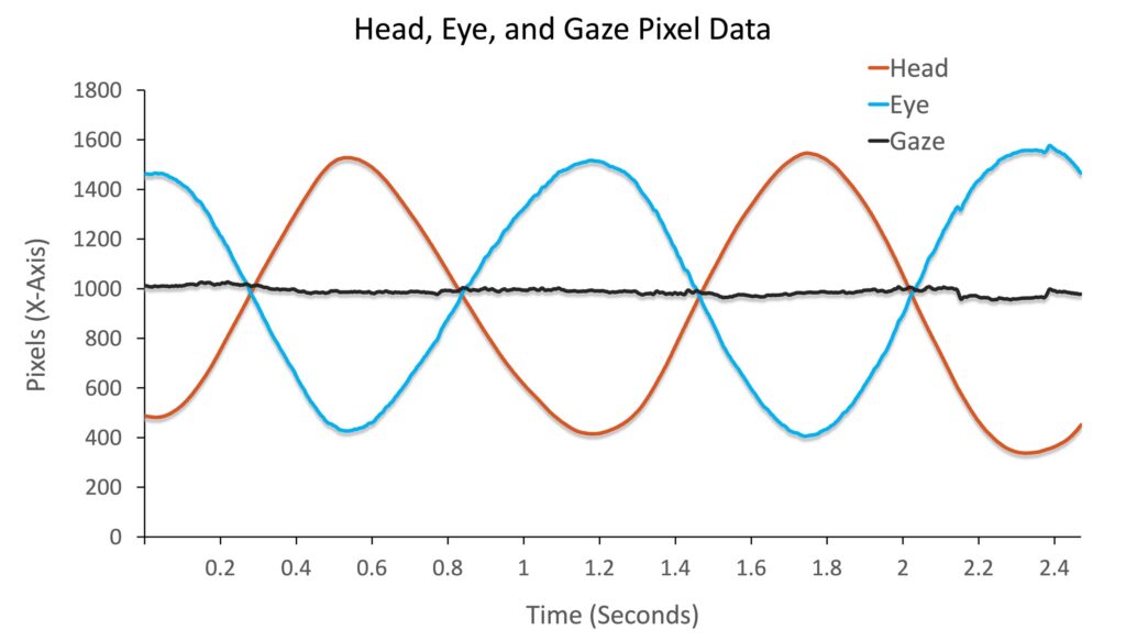
To view the complete disassociation between head, eye, and gaze data across time, the plot below illustrates the three pixel-based data types as a participant makes “yaw” head rotations (i.e., shakes head back and forth) whilst maintaining fixation on a central target. The gaze data remains unchanged, approximately fixed at the center of the screen along the X-axis, but the head and eye data change in opposite directions – as the eye counter-rotates within the head to maintain the fixation.
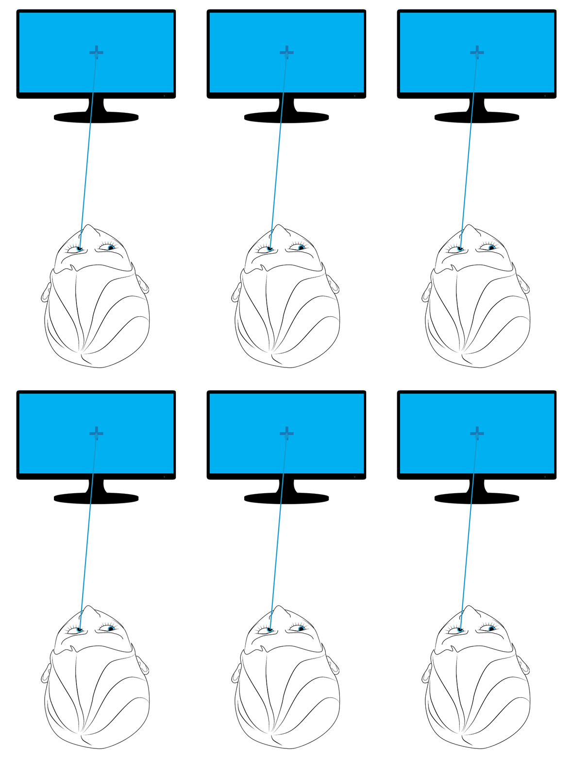
Figure 8 : Pixel-based coordinates along the X-axis while head and eyes move in opposite directions to maintain central fixation.
结论
In addition to providing full 6DOF head position and rotation data and pixel-based gaze data, the EyeLink 3 eye tracker also provides novel head and eye pixel-based coordinates. This data provides a simple and convenient solution for determining the relative contributions of head and eye movements to gaze shifts made in traditional eye tracking tasks such as visual search, scene perception, reading, prosaccades and smooth pursuit. All the data is available in the recorded data file and is streamed to the stimulus display PC in real time. This opens up the possibility of developing novel tasks, including head- or eye-contingent tasks.
联系
If you would like more information on the EyeLink 3, you can call us (+1-866-821-0731 or +1-613-271-8686) or click the button below to email: