Estimated reading time: 6 minutes
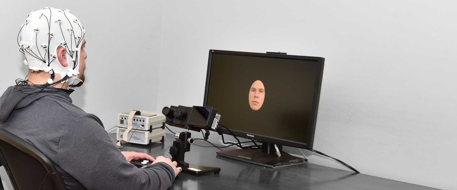
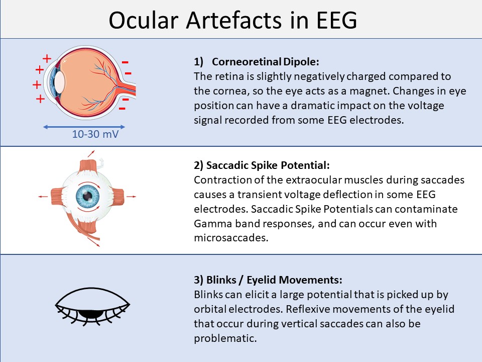
Researchers are increasingly aware of the benefits of combining eye tracking with EEG and other neurophysiological recording equipment. One of the most common rationales for recording simultaneous EEG and eye-tracking data is “artifact rejection.” Blinks and eye movements themselves (even tiny microsaccades) can have a profound impact on the EEG signal and cause significant problems for subsequent analysis. Accurate eye-movement recordings allow researchers to confidently identify and reject contaminated trials.
Another benefit of combined EEG and eye tracking is that live gaze data can be used to control stimulus presentation. In other words, gaze-contingent tasks can be implemented, such that stimuli are only presented when participants are fixating a central target for example.
More recently, EEG researchers have begun to exploit the rich information that gaze data provides concerning what information is currently being processed, to develop techniques such as “fixation event-related potentials” (fERPs). In this approach, the gaze data recorded by the eye tracker ceases to be merely an indication of potential contamination in the EEG signal, or as a means to control stimulus presentation. Instead, fixation onsets (for example to critical areas of a scene or words in a sentence) are used to define epochs in the EEG data for subsequent ERP detection.
Synchronizing Eye-Tracking and EEG Recordings
An important consideration when collecting simultaneous eye-tracking and EEG data is how to synchronize the two data streams. “Clock drift” between the two recording computers can mean that 10000ms in one recording may not equate to exactly 10000ms in the other. This problem is typically overcome by sending common “marker” signals into both data streams, which can be used to align the data at the analysis stage.
There are four ways in which such synchronization can be achieved between EyeLink eye trackers and EEG equipment:
1) TTL Signalling
TTL stands for Transistor-Transistor Logic – paired transistors allow voltage to be rapidly changed between <0.8v (“low” or 0) or > 2.4v. (“high” or 1). Nowadays the term TTL is often used to refer to the signal itself, rather than the mechanism behind it. TTL signaling has a long history, and whilst it may seem somewhat out-dated, it remains a popular means by which to integrate equipment in laboratories – not least because it is “tried and tested” and has excellent and reliable timing properties. Computers typically send TTLs via a Parallel Port – an increasingly rare feature that in the past was mainly used for communicating with line-printers – indeed it is still often referred to as the LPT port. Nowadays, devices such as the USB2TTL8 can be used with computers that do not have an actual parallel port.
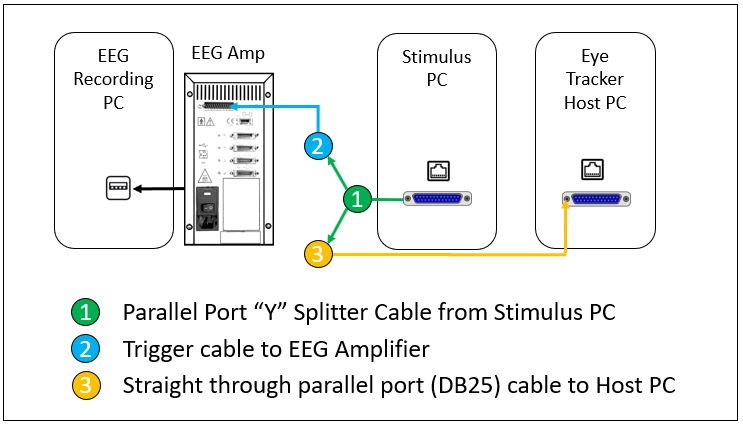
In the simplest form of TTL integration, a stimulus PC sends TTLs (a number between 0 and 255 that gets translated into High or Low voltages on the 8 pins of the “data register” of the parallel port) that mark the onsets of critical trial events. The TTL signals are sent simultaneously (via a splitter or “Y” cable) to both the Host PC and the EEG device. Thus both data streams receive common event markers which can be used to synchronize the data at the analysis stage.
2) Combined TTL and TCP/IP Signalling
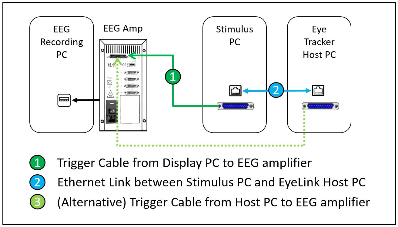
This is a very popular approach among EyeLink users, as it takes advantage of the Ethernet connection between the Display PC and Host PC. As with the approach above, a TTL signal is sent from the Display PC to the EEG recording equipment, typically signaling the onset of key trial events. Instead of the TTL signal being sent to both the EEG equipment and to the Host PC, a simultaneous message is sent to the Host PC via the ethernet link. At the analysis stage, the TTL can be matched with its associated message in order to synchronize the two data streams. In a variant of this approach, a command is sent to the Host PC via the ethernet link, telling it to send the TTL from its parallel port. This can be particularly useful if your Display PC does not have a parallel port of its own.
3) TCP/IP Integration
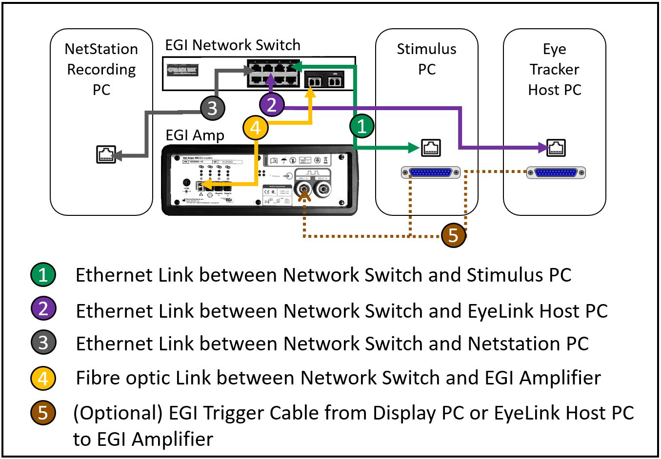
Some EEG systems, most notably Philips-EGI systems, can be fully integrated via TCP/IP signaling. All three computers are connected to a single network switch, and Network Timing Protocol is used to synchronize all communication and trigger sharing.
4) Analog Output
The final integration solution available to EyeLink users is the Analog Output option, which can be added to Desktop Host PCs. The add-on DAQ card converts the digital data on the host PC to analog voltages that are output in real-time (three channels for each eye: horizontal position, vertical position, and pupil size). These analog signals can be inserted into empty channels in the EEG/MEG device, providing a record of eye position that is already lined up with your EEG/MEG data. Whilst this solution is convenient in some settings, the D/A and A/D conversions add some noise to the data, and sending these voltages along cables can also allow further noise to be introduced.
Post-Hoc Synchronization
In the first three approaches, once data has been collected, software such as EEG-LAB and the EYE-EEG add-on can be used to align the data based on the common TTL / Messages. Version 2.2 of our stimulus presentation software, Experiment Builder, has dedicated nodes that facilitate all of these synchronization strategies. Don’t hesitate to contact our support services if you have any questions about integrating your EyeLink system with EEG – we’re always happy to help!
Contact
If you would like us to feature your EyeLink research, have ideas for posts, or have any questions about our hardware and software, please contact us. We are always happy to help. You can call us (+1-613-271-8686) or click the button below to email:
